How To Use Aluminum Alloy Formwork For Construction?
May 07, 2021
The whole construction process of the aluminum alloy formwork system is as follows:
Architectural drawings and structural drawings are designed → aluminum alloy formwork technicians review drawings and quotations → negotiate cooperation content and sign contracts → technicians design matching patterns (template assembly drawings) → produce according to drawings → factory pre-assembly (by 2020, the factory) Has been able to achieve pre-assembly) → qualified inspection → factory, delivery → construction site.
Construction process of aluminum alloy formwork:
1. Play the wall column line and the wall column control line and the opening line on the floor. The wall column control line is 200mm from the wall edge line. It can be checked whether the template is offset and square; mark the floor elevation control point on the column longitudinal reinforcement. The four corners and corners of the wall pillars are set up to check the floor elevation.
2. Install wall column steel bars and embedded water and electricity boxes, line pipes, reserved openings, etc., and go through the acceptance procedures for concealed works after completion.
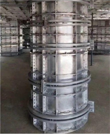
3. Install the wall column template
(1) During the initial installation of the formwork, the positioning bricks are fixed on the concrete surface with nails to the inside of the outer corner formwork to ensure that the formwork installation is aligned with the stakeout line.
(2) All templates are installed from the internal corners, so that the templates can remain stable laterally. A template at the corner can provide sufficient lateral support for a long wall form.
(3) Before installing the template, ensure that all contact surfaces and edges of the template have been cleaned and painted with release agent.
(4) When the corner is stable and the inner corner mold is positioned according to the lofting line, continue to install the entire wall mold. In order to facilitate removal, the head of the pin should be as close as possible to the inside of the inner corner mold when the wall mold is connected to the inner corner mold.
(5) Before closing the formwork, it is necessary to pre-coat the PVC pipe on the wall form connector, and at the same time ensure that the contact position of the sleeve and the formwork on both sides of the wall is accurate, so that the opposing screws can be retracted after pouring.
(6) When the outer wall is deviated, it must be adjusted to the correct position as soon as possible. This only needs to be slightly tilted in a plane. If there is a vertical deviation in two directions, it is necessary to adjust more than two floors, one level adjustment one direction. Do not try to adjust the alignment of the template by unilateral lifting. If there is a large deviation, some concrete needs to be chiseled to meet the requirements.
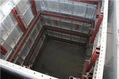
4. Install beam and top plate mold
(1) Before installing the wall top side mold and beam angle mold, apply a release agent on the contact surface of the component and the concrete.
(2) When the wall top side mold and beam corner mold are connected to the wall formwork, pins should be inserted from the upper part to prevent the pins from falling off during pouring. After installing the top side mold of the wall, you can start to install the board mold at the corner. It is necessary to ensure that the contact side has been coated with a release agent.
(3) The slab beam is used to support the slab mold. In most cases, the slab beam should be assembled according to the layout of the slab mold. Use long pins and two ribs to connect the slab-girder assembly to the two adjacent slab support beams.
(4) Install the tool-type column on the pre-installed beam assembly in the direction of the beam. This can protect the bottom of the tool-type column when the tool-type column is removed.
(5) Lift the beam to the proper position with a tool-type column. Through the end of the plate mold that has been installed at the corner, the beam and the plate mold are connected with a pin.
(6) Ensure that the frame of the board support beam has been coated with release agent before installation.
(7) The first formwork in each row has been connected to the top side formwork of the wall and the supporting beam. The second template only needs to be connected to the first template. The second template is not connected to the crossbeam in order to have enough adjustment range when placing the third template in the same row. After the third template and the second template are connected, the second template is fixed on the crossbeam. Use the same method to place the remaining templates in this row.
(8) Many rows of top plates can be installed at the same time, and the mold release agent can be applied on the top plate mold surface before laying steel bars.
(9) For beams and slabs with a span greater than 4m, the arching height of the formwork should be the span of the component (1/1000-3/1000). After the top plate is installed, the elevation of all formwork surfaces should be checked. Add a pad at the bottom of the tool-type column to adjust the level. [2-6]
(10) Provide work benches for construction personnel when installing floor formwork.
(11) The aluminum alloy formwork quick release system requires the material transfer port to be reserved on the top plate. After the design unit agrees, the number, size and location of the material transfer port are determined, so that after the template is removed, the template can be directly transferred through the material transfer port. Up to the upper floor, thereby reducing the setting of the unloading platform, reducing the use of tower cranes, ensuring the safety of formwork transfer construction, and reducing the use of machinery.
5. Install the wooden starting board
(1) Where there are continuous vertical templates, such as elevator shafts, external walls, etc., use the outer starting board of the wooden mold to enclose the floor slab in a closed circle and serve as the connecting component of the vertical template of the upper layer.
(2) After the first layer is poured, the second layer will be connected to the K board as the starting point of the next layer of wall formwork
(3) The K board starting board is connected with the wall template. Before installing the K board, make sure that the cleaning and oiling work has been completed. In order to prevent the pins from falling off during pouring, the pins must be inserted from the lower frame of the K plate into the upper frame of the wall.
(4) Open a 16.5mm oval hole on the periphery of the K plate. Before pouring, install the M16 bolts at the position close to the bottom of the groove. These bolts will be anchored in the solidified concrete. After pouring, if necessary, the bolts can be adjusted to adjust the horizontality of the periphery of the K plate, which can also control the verticality of the formwork.
(5) For the positioning of the K-board starting board, use a hanging wire to check the positioning of the K-board peripheral starting board: the straight K-board peripheral starting board can ensure the straightness of the next layer of wall formwork.